Post-Use Capsule Separation Mechanism
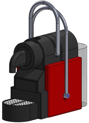
Mechanical re-engineering of a Nespresso Turmix Pixie single-serve coffee machine, adding an integrated mechanism that opens each used capsule, removes the coffee ground, and sorts it from the aluminum shell. The retrofit fits inside the machine's original footprint, adds no operating energy, and needs under 10 N of user effort.
Objective
Re-engineer an existing single-serve coffee machine so that, immediately after brewing, it also opens the spent capsule, removes the coffee ground, and keeps the aluminum shell and the coffee ground in two clean, separate waste streams, without a clean-sheet redesign of the base platform.
- 1Retrofit onto the existing Nespresso Turmix Pixie machine's footprint, body, and lever kinematics. This is a modification, not a new product.
- 2Remove at least 80% of the coffee ground from each capsule, with zero cross-contamination between the two waste streams.
- 3Provide on-board storage for at least a week of typical household use (≥ 15 capsules) for both waste materials.
- 4Keep the added operating force low enough for any adult user, regardless of age or sex, to operate comfortably, and low enough that the machine does not slide on the counter.
- 5Cap the increase in weight, volume, energy draw, noise, and unit cost against fixed percentages of the original machine (full targets in Section 4).
The Redesigned Machine
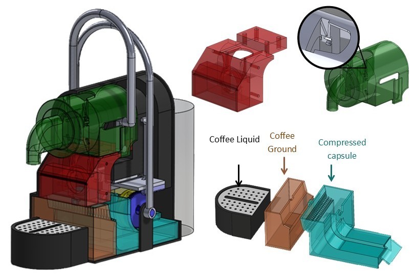
A compression module was retrofitted below the original dripping compartment, sharing its lever and water circuit. A used capsule now falls automatically into a rail, is crushed by a piston driven from a second lever, and its coffee ground and aluminum shell separate into two on-board storage bins.
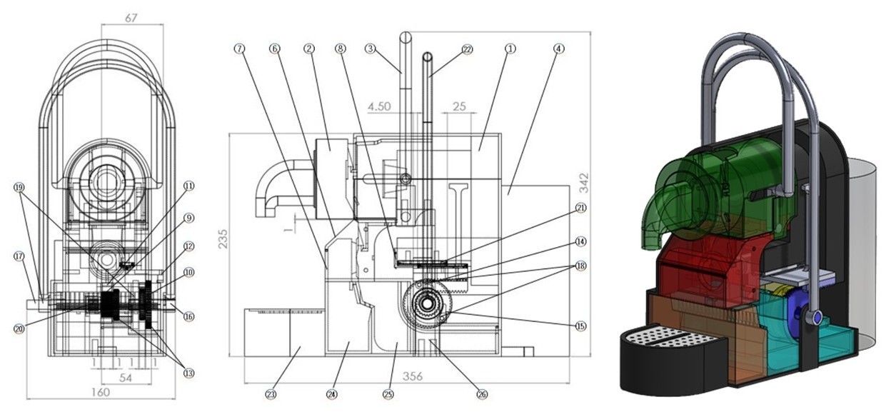
| No. | Part | Qty. |
|---|---|---|
| 1 | Body | 1 |
| 2 | Dripping Compartment | 1 |
| 3 | Original Lever | 1 |
| 4 | Water Tank | 1 |
| 5 | Side Plate | 2 |
| 6 | Compression Compartment | 1 |
| 7 | Door of Compression Compartment | 1 |
| 8 | Door of Compression Compartment | 1 |
| 9 | Gear Small | 1 |
| 10 | Gear Large | 1 |
| 11 | Rack Small | 1 |
| 12 | Rack Large | 1 |
| 13 | Ratchet Wheel | 2 |
| 14 | Ratchet Craw Small | 1 |
| 15 | Ratchet Craw Large | 1 |
| 16 | Shaft Small | 1 |
| 17 | Ratchet Plate Shaft | 1 |
| 18 | Spring for Ratchet | 2 |
| 19 | Bush | 2 |
| 20 | Bearing | 1 |
| 21 | Linear Rail | 1 |
| 22 | Lever New | 1 |
| 23 | Cup Stand | 1 |
| 24 | Box for Coffee | 1 |
| 25 | Box for Aluminum | 1 |
| 26 | Base for Gear & Ratchet | 1 |
| N/A | Screw M6×22 | 4 |
| N/A | Screw M4×15 | 4 |
| N/A | Screw M4×10 | 2 |
| N/A | Screw M2×15 | 3 |
| N/A | Screw M2×10 | 6 |
Method
The redesign followed the systematic engineering design process standard in mechanical product development: decompose the existing machine into functions, generate and screen concepts, select and de-risk the winning concept, then engineer and verify every loaded component before releasing the design.
- Concept generation used a morphological matrix of working principles, screened down to three feasible concepts.
- The winning concept was chosen with a weighted decision matrix, confirmed by a two-pass sensitivity analysis.
- Technical risks were ranked with FMEA-style probability × severity scoring, a Six Sigma risk-analysis tool, before detail design began.
- Piston geometry and mechanism force targets were set from physical prototype testing, not assumption alone.
- Every loaded component was checked against a hand or finite-element (Abaqus) stress calculation before release.
- All CAD modeling, 2D drawings, and BOM generation were done in SolidWorks.
Customer Requirements & Functional Decomposition
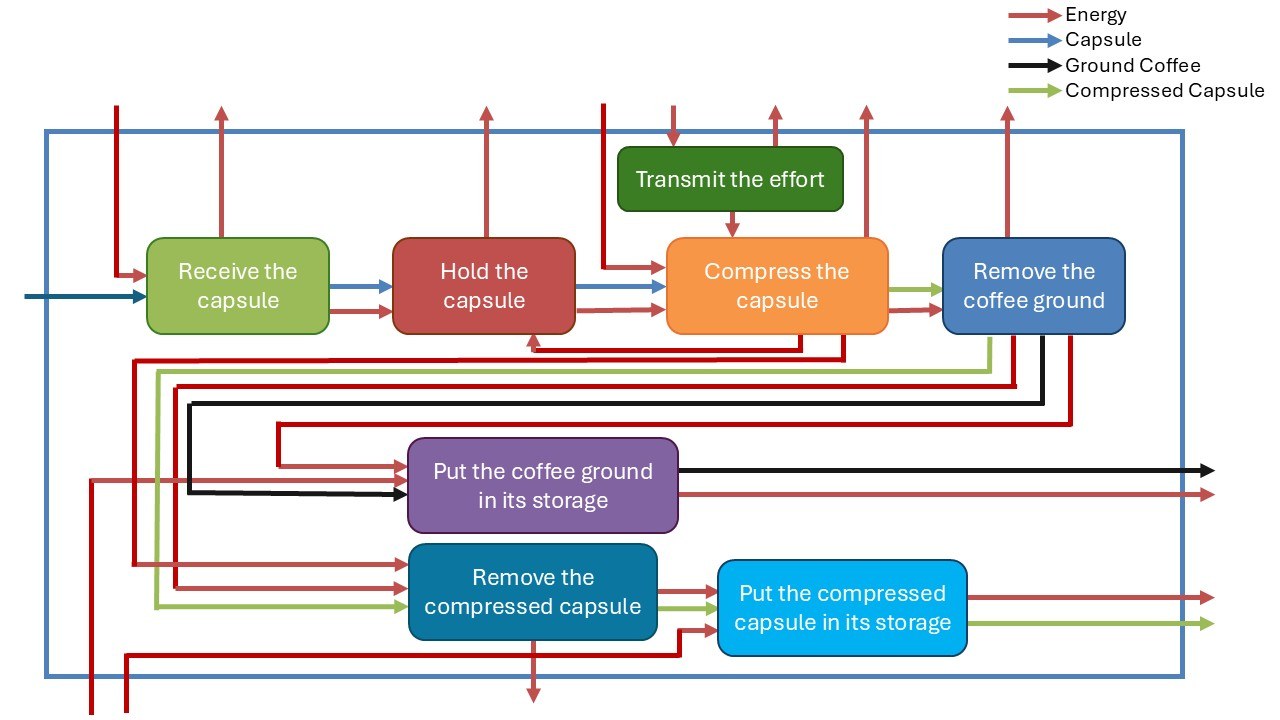
The new task was broken into six sub-functions: receive, hold, open, remove the coffee ground, then guide and store each material separately. This structured both concept generation and the final part list (Section 6).
| No. | Requirement | Category | Target |
|---|---|---|---|
| 1 | Output segregation | Need | Aluminum shell and coffee ground fully segregated, zero cross-contamination |
| 2 | Coffee ground removal | Need | ≥ 80% of coffee ground removed per capsule |
| 3 | Storage capacity | Need | ≥ 15 capsules of combined waste, on-board |
| 4 | Cleanliness | Need | Parts contacting coffee ground are hand-removable and cleanable |
| 5 | Cycle time | Need | Capsule processed faster than one brew cycle (≤ 35 s) |
| 6 | Dimensions | Wish | ≤ 25% increase in overall machine volume |
| 7 | Weight | Wish | ≤ 40% increase in machine weight |
| 8 | Safety | Need | No exposed sharp edges; safe for unsupervised domestic use |
| 9 | Noise | Need | ≤ 80 dB per cycle (5 s allowance to 85 dB) |
| 10 | Accessibility | Wish | Operable with the same ease as the stock machine |
| 11 | Maintenance | Need | Maintainable by an average user, no special tools |
| 12 | Unit cost | Wish | ≤ 40% increase in unit cost |
| 13 | Energy draw | Wish | ≤ 40% increase in the machine's operating energy draw |
| 14 | Appearance | Wish | Preserve the machine's original visual character |
A short prior-art review of patented capsule-separation mechanisms (a three-piston, motor-driven design) confirmed the core difficulty: existing approaches opened the capsule well but grew the host machine considerably to fit the extra hardware. That finding shaped Requirement 1 and steered concept generation (D1) toward a compact, single-actuator solution.
Results
All 14 customer requirements are met by the final design. Two close with a genuinely tight margin, and one usability trade-off was accepted deliberately. All three are carried into the recommendations in Section 7 rather than smoothed over here.
Allowance used, by requirement
Share of each capped requirement's allowable increase (or force limit) already used. Hover a bar for details.
| No. | Requirement | Target | Achieved | Status |
|---|---|---|---|---|
| 1 | Coffee ground removal | ≥ 80% | 85% average | Satisfied |
| 2 | Storage capacity | ≥ 15 capsules | 15 capsules | Satisfied |
| 3 | Cycle time | ≤ 35 s | 13 s | Satisfied |
| 4 | Volume increase | ≤ 25% | 5% | Satisfied |
| 5 | Weight increase | ≤ 40% | 39.2% (3.9 kg) | Satisfied, tight margin |
| 6 | User force, ergonomic ceiling | ≤ 25 N | 9.85 N | Satisfied |
| 7 | User force, anti-slip ceiling | ≤ 12 N | 9.85 N | Satisfied, tight margin |
| 8 | Noise increase | ≤ 80 dB | ≈ 0% increase | Satisfied |
| 9 | Energy draw increase | ≤ 40% | 0% (no motor) | Satisfied |
| 10 | Unit cost increase | ≤ 40% | Met only at high volume | Conditional |
| 11 | Cleanliness | Hand-cleanable parts | Storage boxes detachable & washable | Satisfied |
| 12 | Safety | No exposed sharp edges | No sharp features in normal use | Satisfied |
| 13 | Maintenance | Average-user maintainable | No parts requiring routine replacement | Satisfied |
| 14 | Accessibility | Comparable to stock machine | Two-lever, two-button sequence | Usability trade-off |
Analysis Detail
Each analysis isolates one engineering decision behind the Section 5 results: concept work first, then risk, testing, mechanism, and the component-level calculations, in the order they were actually worked.
Concept Generation
Six required sub-functions were expanded into a morphological matrix of working principles (rail-and-gravity feeds, mandrels, guillotines, brushes, piercing spikes, compression pistons), combined into eight candidate concepts, then screened down to three feasible directions:
Peeling: capsule held like a drill chuck and peeled open
via combined rotation + linear screw motion (2 DOF); low force, but needs a motor and a tightly
toleranced cutting path.
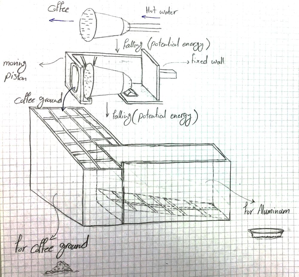
Compression: falling capsule crushed against a fixed wall
by a user-driven piston; 1 DOF, no motor.
Mandrel: capsule clamped, rim sheared by a guillotine,
contents excavated by a drill; best coffee removal, most parts and space.
Concept Selection
A weighted decision matrix scored the three feasible concepts against seven criteria drawn directly from the customer requirements, then a two-pass sensitivity analysis re-ran the matrix with different weight sets to confirm the winner wasn't an artifact of how the weights were chosen.
| Criterion | Weight | Peeling | Compression | Mandrel |
|---|---|---|---|---|
| Coffee removal | 0.13 | 3 | 1 | 3 |
| Maintenance | 0.14 | 2 | 3 | 1 |
| Occupied space | 0.15 | 1.5 | 2.5 | 1 |
| Ease of use | 0.18 | 3 | 2 | 3 |
| Mechanism DOF | 0.21 | 1 | 3 | 1 |
| Energy | 0.08 | 2 | 3 | 2 |
| Noise | 0.11 | 2 | 3 | 2 |
| Weighted total | 1.00 | 2.03 | 2.49 | 1.81 |
Two additional weight sets shifted the totals to 2.23 / 2.22 / 1.99 and 2.09 / 2.49 / 1.91 (Peeling / Compression / Mandrel). The Compression concept won or effectively tied in every weighting, so it was carried into embodiment despite scoring lowest on coffee-removal quality alone, a gap closed directly in D4.
Risk Analysis (FMEA-Style)
With a concept selected, the technical risks were ranked using an FMEA-style probability × severity scoring approach (a standard Six Sigma risk-analysis tool) before committing to detail design, so the highest risk-priority items received engineering attention first rather than just the most obvious ones.
| Risk | P | D | RPN | Mitigation carried into design |
|---|---|---|---|---|
| Machine exceeds the weight budget | 3 | 5 | 15 | Metal parts (especially the piston) designed hollow instead of solid stock |
| Capsule jams in the feed rail | 3 | 5 | 15 | Reused the existing, proven rail geometry from the dripping compartment |
| Compressed capsule jams in the mechanism | 3 | 5 | 15 | Piston-head edges plus a matching cover edge strip the capsule into storage |
| Required lever force too high for some users | 3 | 4 | 12 | Doubled the compression stroke via a ratchet, halving peak force per stroke |
| Coffee ground removal below 80% | 3 | 4 | 12 | Concave piston-head geometry and 20 mm diameter set from testing (D4) |
| Machine slips on the counter during use | 3 | 4 | 12 | Lever force kept near 10 N, under the calculated 12 N slip threshold |
| Machine loses stability / tips | 2 | 5 | 10 | Center of mass and new lever hinge kept low relative to the original design |
Four lower-priority risks (RPN 1–8) covered coffee-ground / aluminum cross-contamination and leakage; all were closed by grid sizing in the storage boxes and a sealed mechanism housing, and none were observed in later prototype testing.
Piston Diameter & Compression Force Testing
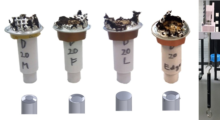
3D-printed piston heads at four diameters were pressed into used capsules on an instrumented test rig (Fig. 5) to find the smallest force that still gave clean, symmetric compression.
| Piston ø [mm] | Avg. max. force [N] | Symmetric? | Coffee removal |
|---|---|---|---|
| 32 | 245 | Yes | 85% |
| 26 | 216 | No | 80% |
| 24 | 206 | No | 80% |
| 20 (selected) | 142 | Yes | 85% |
Both 32 mm and 20 mm gave symmetric compression with 85% coffee removal; 20 mm was selected for needing far less force to do it (142 N vs. 245 N).
Ergonomic & Anti-Slip Force Limits
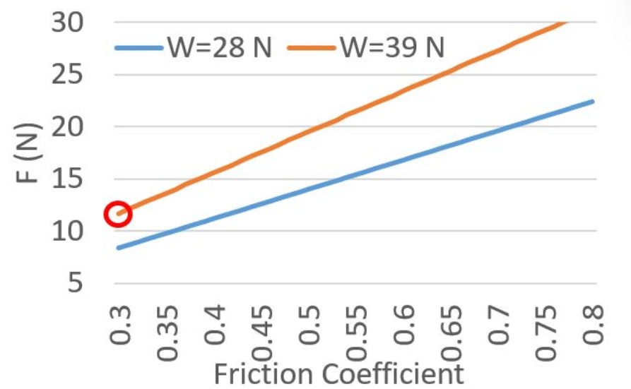
Published hand-pulling-strength data set a hard ceiling of 25 N (the low end for women at age 55). A simplified 2D slip model at the design weight (3.9 kg) then tightened that further: at the existing rubber feet's friction coefficient (≈ 0.3), the machine begins to slide above roughly 12 N of lever force.
Both limits became binding constraints on the mechanism (D6), not just the piston.
Mechanism Selection: Double-Ratchet & Dual-Gear
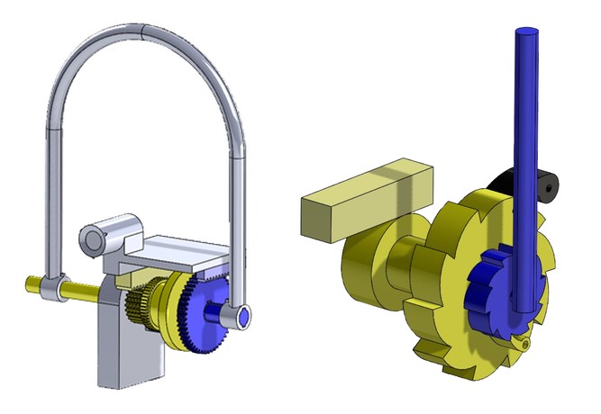
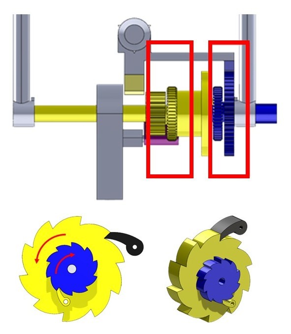
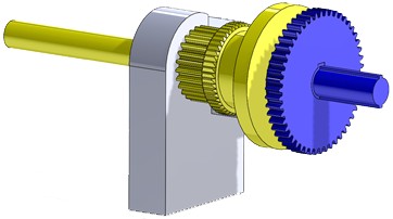
Six lever/gear layouts were screened for force-transmission linearity and synchronization between the dripping and compression compartments. A rack-and-gear layout with the compression compartment fixed in place won on both counts, but even so, a single 90° lever stroke could not bring user force under the 12 N ceiling from D5. Splitting the stroke into two 90° pulls (using a double-ratchet mechanism so the gear only advances on the power stroke) halved the peak force per pull. A second gear, engaged only on the return stroke, then resets the piston with a single lever lift.
FEM Stress Check: Cover Part (Abaqus)
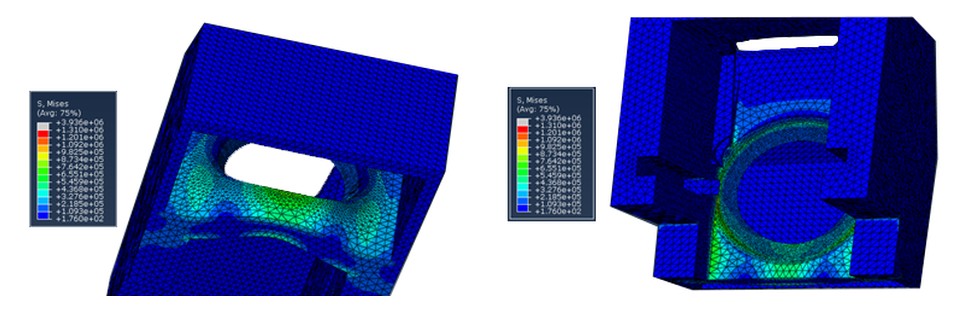
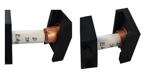
The molded cover part must survive repeated compression-reaction loading around the coffee-ground discharge hole without cracking. Solved in Abaqus with a tetrahedral free mesh, global element size 1 mm, refined to 0.5 mm around the hole.
Even against the low end of the ABS yield range, the peak stress leaves better than a 4× margin, confirmed separately by a 3D-printed prototype that survived the same loading in testing (Fig. 9).
Gear Design: Material Selection
The high-load compression gear (25 mm dia., module 1, 25 teeth, 20° pressure angle) must clear both Hertz contact stress and bending stress at the compression mesh, with no interference risk. Six candidate steels were checked against the minimum gear thickness each would need.
| Material | σ adm H [MPa] | σ adm F [MPa] | Min. thickness [mm] |
|---|---|---|---|
| Ac 60 | 400 | 200 | 25.6 |
| CK 45 (selected) | 590 | 200 | 11.8 |
| 37 Cr 4, hardened | 650 | 270 | 9.7 |
| 37 Cr 4, quenched | 1280 | 310 | 9.5 |
| 42 CrMo 4, nitrided | 1220 | 430 | 2.75 |
| 20 MnCr 5, case-hardened | 1630 | 480 | 2.28 |
CK45 was selected over the higher-grade alloys: it clears the requirement at a practical thickness without paying for hardening or case-carburizing that this load case doesn't need.
Shaft & Wedge Stress Check
The shaft carrying gear torque during compression must stay comfortably below the CK45 yield strength in torsion, and the drive key (wedge) transmitting that torque must clear both shear and bearing (matting) stress limits.
A 10 mm shaft leaves roughly 25× margin against yield in torsion, more than the load needs, and flagged in Section 7 as a candidate for a lighter revision. The Type-B drive wedge (a = 2 mm, L = 13 mm) checks out at ≈ 50 MPa bearing stress, inside the 40–150 MPa window for a fixed steel key, with shear stress held under half the material's yield strength.
Bearing & Linear Slide Selection
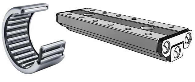
The piston needs a linear guide that can absorb the radial load and torque the gear/rack mesh feeds into it, and the ratchet shaft needs a bearing that carries radial load while still allowing it to slide axially between its two clutch positions.
An SKF LVZ7 linear slide (50 mm stroke) was selected off the shelf: the applied load uses only ≈ 3% of its rated capacity, leaving ample margin for the torque component not captured in the simplified radial check. A needle bearing was chosen for the ratchet shaft for its high radial capacity, low cost, and because it does not resist the shaft's axial sliding motion.
Manufacturing & Cost (DFM/DFMA)
A rough should-cost estimate was built from the added mechanism's Bill of Materials to check the cost increase against the customer's ceiling, before recommending a full DFMA pass with a manufacturing partner.
The ≤40% cost-increase requirement is missed at prototype/unit volumes but closes at high production volume, where purchased-component pricing (bearing, linear slide, gears, springs) typically falls by more than half. This is flagged in Section 7 as needing a real supplier quote rather than the linear scaling assumption used here. Material selection followed directly from D7–D8: ABS for the molded housings (lightweight, low-cost, ample FEA margin) and CK45 carbon steel for the loaded gear-train components, chosen for its Hertz/bending-stress-to-cost ratio over the higher alloy grades considered.
Final Assembly & Operating Sequence
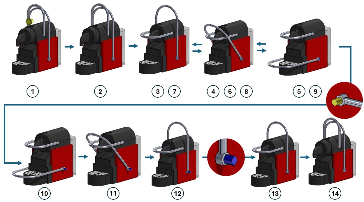
- 1Load a new capsule into the dripping compartment (the previous used capsule already sits in the compression compartment below).
- 2Brew as normal: pulling the original lever drips coffee and, at the end of its stroke, drops the used capsule into the compression rail.
- 3Pull the new compression lever down and up twice (2×90°) to drive the piston through the capsule.
- 4Press the release button to free the ratchet, then lift the lever once to send the piston back and drop the crushed capsule into storage.
Engineering Judgment & Recommendations
Beyond the pass/fail result, the project surfaces where the design has real room and where it doesn't.
⚠ Weight sits at 98% of its allowance
3.9 kg against a 40% cap leaves only 0.8 percentage points of headroom. Recommend a follow-up lightweighting pass (further hollowing of the piston and base, or swapping select CK45 brackets for aluminum) before committing to production tooling.
⚠ Anti-slip force margin is the tightest constraint on the mechanism
At 9.85 N against a 12 N slip ceiling, this (not the 25 N ergonomic limit) is what actually bounds the mechanism. If a future revision changes the machine's weight or foot material, this is the constraint to re-check first.
Usability trade-off: two levers, two buttons
The double-ratchet solution keeps user force low but adds manipulation steps versus the stock machine. Recommend investigating a single-lever alternative, or automating the gear-change step (e.g. cable-actuated from the compression lever) in a future revision.
Unit cost needs a real supplier quote
The €135.5 / €67.75 cost-increase estimate uses a linear volume-scaling assumption on purchased components. Before sign-off, replace it with quoted pricing from a manufacturing partner and a proper DFMA review.